P&ID Symbols: How to Read Symbols for Valves, Components, Process Lines & More [w/ Download]

George Packard
Read Full Bio
Piping and instrumentation diagrams (P&IDs) are conceptualized during the development and design stages of chemical, physical, electrical and mechanical processes. Everything from ball valve symbols to communication lines are included in a P&ID in order to lay out the proper direction for a process control installation.
In this article, we highlight some of the most common P&ID valve symbols, process lines, end connections and other vital components. Before you dive in, get your copy of the valve symbols discussed in this post.
What Is a Piping & Instrumentation Diagram?
A P&ID is a detailed, visual representation of a process system. P&IDs include standard symbols that explain:
- Component identification
- How instruments are connected
- Where instruments are located
- The instruments’ function within a process
The symbols for these components aren’t drawn to scale and aren’t intended to be dimensionally accurate. Symbols can also be marked with words, letters and numbers for more detail.
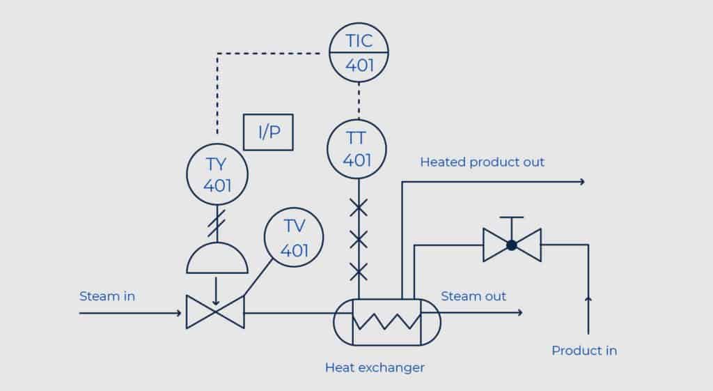
Below is an example of a P&ID for a heat exchange process:
How Are P&IDs Used?
The purpose of a P&ID is to illustrate a system’s process. P&IDs are used for the design and maintenance of the manufacturing processes they represent, and are imperative for troubleshooting and process monitoring.
Since they aren’t drawn to scale, P&IDs should not be used as a map or floor plan of the system.
P&IDs vs. PFDs
P&IDs are often confused with process flow diagrams (PFD). However, a PFD is more of a high-level depiction of a process and doesn’t include as much detail as a P&ID.
Standardization
The International Society of Automation (ISA) created the ANSI/ISA-5.1-2009 standard that defines the proper ways to use symbols in a P&ID. Although these standards are in place, there may be variations of certain symbols used across industries or companies. But, since all components in a P&ID use text or numbers for further identification, having a basic understanding of the symbols should not be an issue.
P&ID Diagram Symbol Categories
P&IDs use basic symbols to define the function of each component in the process.
These include the following categories:
Valves
Actuators
Failsafe Positions
End Connections
Process Lines
Signal Lines
Vessels
Pumps, Fans & Compressors
Sensors, Transmitters & Meters
Tag Numbers
Want to skip the scrolling? Get a PDF version of this post delivered right to your inbox. >>
Valve Symbols
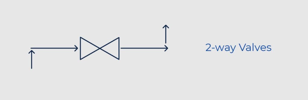
2-Way Valves
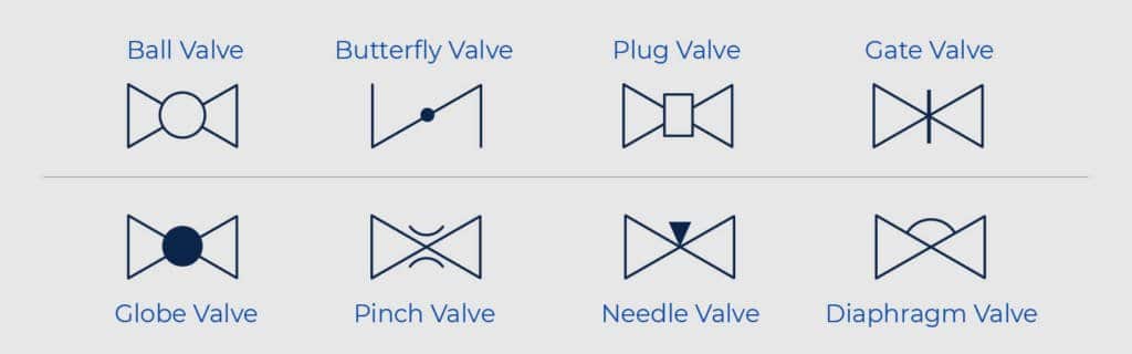
A 2-way, on/off valve is represented by two equilateral triangles that point toward each other. Types of 2-way valves are represented by different types of lines. The direction of the flow is shown by an arrowhead at the end of the line.
The most commonly depicted 2-way valves include:
- Ball Valve
- Butterfly Valve
- Plug Valve
- Gate Valve
- Globe Valve
- Pinch Valve
- Needle Valve
- Diaphragm Valve

Looking for a specific type of ball valve? We’ll help you find the exact parts you need for your project. >>
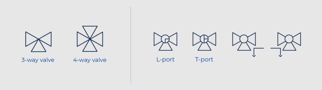
3-Way & 4-Way Valves
For multi-port valves, additional triangles are added to the symbol. L-port and T-port valves are depicted by lines within the ball symbol. The flow path is depicted by small arrows by the symbol.
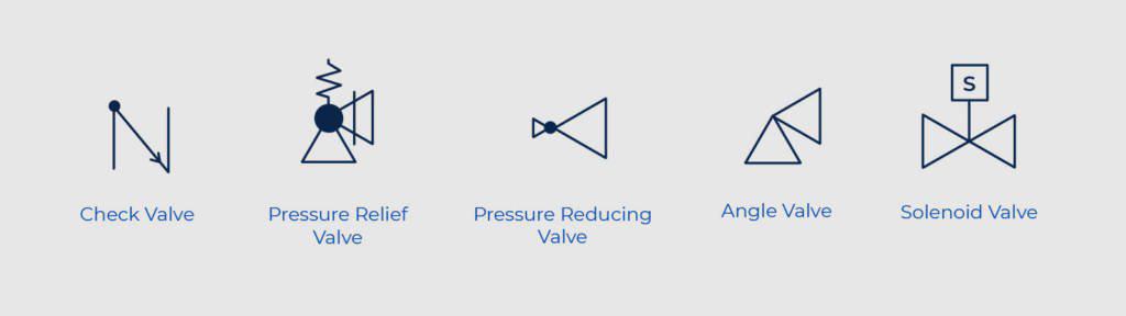
Other Types of Valves
Additional valves are depicted as:
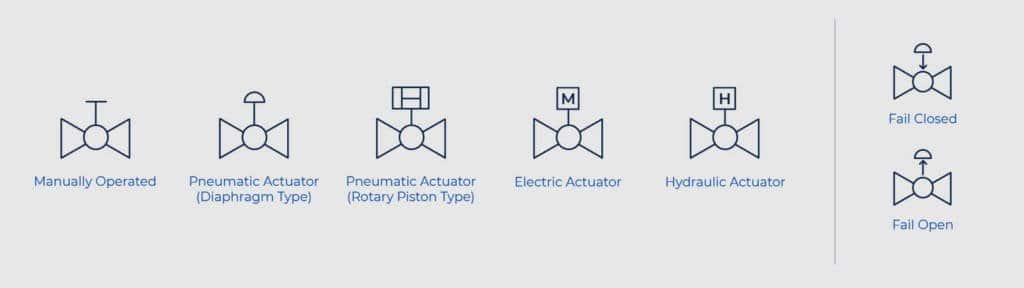
Actuators
The type of actuation is depicted with lines protruding from the center of the valve symbol. A separate small symbol appears on top of the line for further identification. Electric and hydraulic actuation are shown with letters.
Failsafe Positions
Actuators with failsafe options are depicted by a line and arrow either pointing toward the ball (failsafe closed) or away from the ball (failsafe open). These can also be defined with the letters “FO” or FC.”
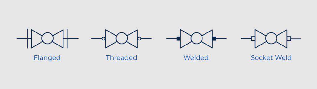
End Connections
The type of connection for a valve (flanged, threaded, welded or socket weld) is displayed using perpendicular lines, circles and squares. For example, the perpendicular lines in a flanged connection show that the valve can be removed without affecting the pipe. Unfilled circles represent temporary threaded connections while permanent welded connections are depicted by filled-in squares. Socket welded connections are displayed using unfilled squares.
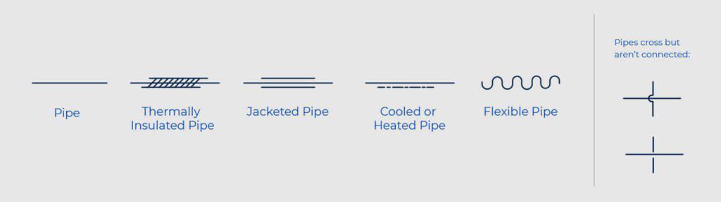
Process Lines
Pipes, tubes and hoses are shown by using different styles of lines. Each line is then labeled with a number, which includes defining information about the component’s class, size, insulation and other factors. If pipes cross but aren’t connected, you can keep them separate in the drawing by breaking one of the lines or adding a curve as depicted below:
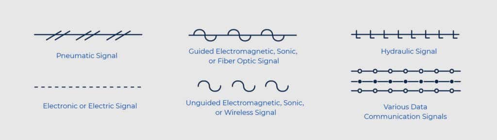
Signal Lines
To communicate information between components, P&IDs include symbols for each type of signal.
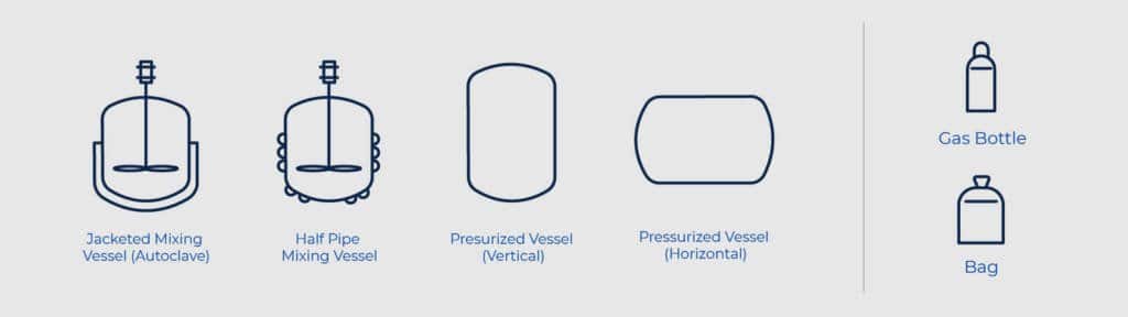
Vessels
Storage tanks, drums and process vessels are depicted using the following standard symbols.
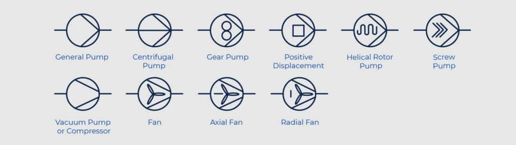
Pumps, Fans & Compressors
Blowers, fume exhausters, air compressors, pressure fans and the like are shown using variations of the following symbols.
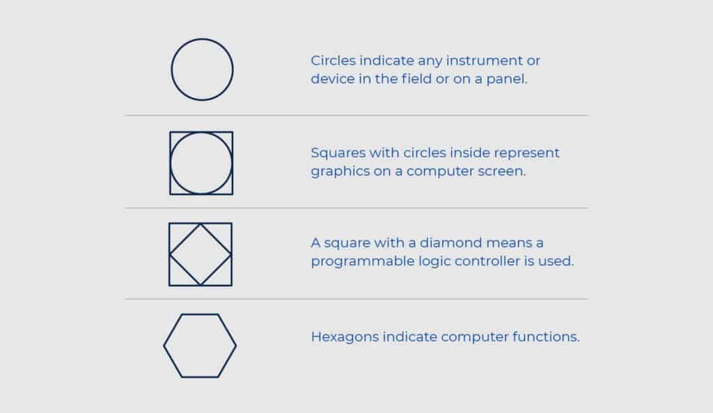
Sensors, Transmitters & Meters
Instrumentation devices — like sensors, transmitters and meters — measure, record and control different parts of the flow process. In a P&ID, these components are shown using various shapes to represent each instrument and explain how they are connected.

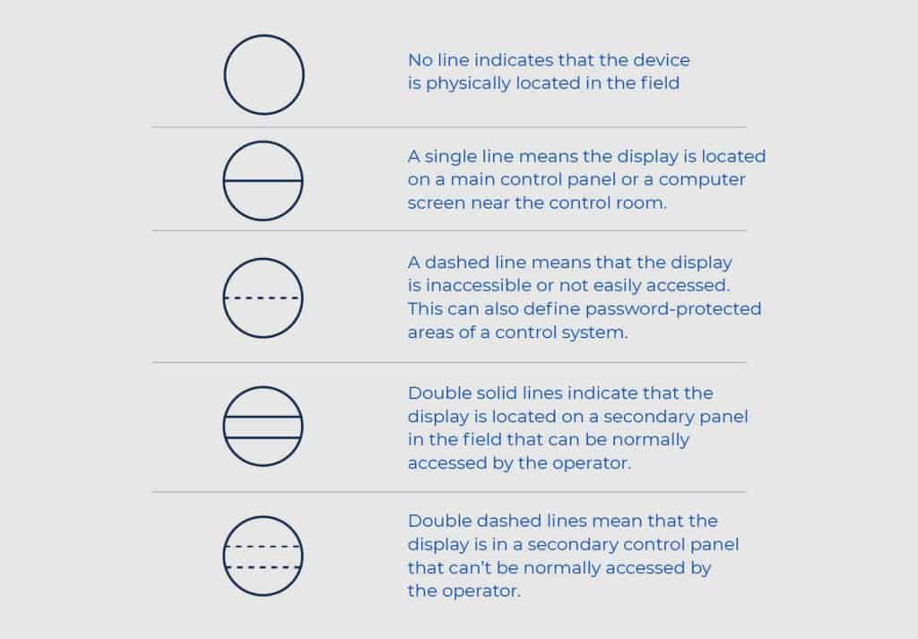
Horizontal lines are also used to define where an instrument is located and if it is accessible.

Tag Numbers
Letters and numbers can be included inside the shapes to further dictate information, such as the property being measured and the function associated with that measurement.
There can be up to 5 letters in a tag:
- The first letter is for the measured value (current, power, pressure, etc.)
- The second letter is a modifier (gas, ratio, difference, etc.)
- The third letter defines the readout/passive function (sensor, indicate, light, etc.)
- The fourth letter is the output/active function (control station, switch, etc.)
- The fifth letter is a function modifier (run, stop, etc.)
The letters are followed by a loop number, which indicates the location and function of the instrument. In the example below, FT is a flow transmitter and the 028 sequence number indicates the location of the device. A sequence number is assigned to all devices within the same function.

Gemini Valve manufactures, distributes and supports a full selection of performance-engineered ball valve products, including custom ball valves. For more information or to speak with a specialist, contact us here.

FAQ
What is the purpose of a P&ID?
The purpose of a piping and instrumentation diagram is to provide a detailed visual representation of a process system that shows how equipment, instruments and piping are connected and controlled. Because they aren’t drawn to scale, P&IDs are meant to only illustrate how a system works, not to be dimensionally precise.
What is the difference between a P&ID and a PFD?
The difference between a process flow diagram (PFD) and a P&ID comes down to the level of detail. A PFD provides a high-level overview of a process, showing the major equipment involved and the general flow of materials. A P&ID takes this illustration further, including all piping, instrumentation, control systems, signal lines and equipment details.
Are P&ID symbols standardized across all industries?
While ANSI/ISA-5.1-2009 sets an established standard that defines how symbols should be used in a P&ID, variations exist across industries and companies. Because all components are also labeled with letters and numbers for identification, having a grasp of the standard symbols makes it easier to interpret most P&IDs, even when minor differences exist.
How do you read tag numbers on a P&ID?
P&ID tag numbers are letter-and-number combinations assigned to instruments that indicate what is being measured and where the instrument is located. A tag can contain up to five letters: the first identifies the measured value (such as pressure or current), the second is a modifier, the third defines the readout function, the fourth is the output function and the fifth is a function modifier. These letters are followed by a loop number that pinpoints the instrument’s location within the system. For example, “FT-028” indicates a flow transmitter at sequence location 028.
What does a ball valve symbol look like on a P&ID?
On a P&ID, a ball valve is represented by two equilateral triangles with their tips pointing toward each other, forming a sideways hourglass shape. A small circle in the center of the symbol represents the ball itself. The type of actuation (manual, pneumatic or electric) is shown by a line and corresponding symbol extending from the center of the valve. For multi-port valves, additional triangles are added to the symbol to indicate the extra flow paths.
George Packard
How to Read P&ID Component & Valve Symbols
In this free, downloadable guide, we highlight some of the most common P&ID valve symbols, process lines, end connections and other vital components.